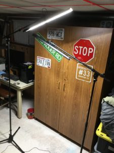
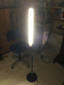
Originally I designed these as wash lighting for stage performance, but I built a second set which does duty as portable workspace illumination. The lights can be hung from an overhead point, strapped to a speaker pole or microphone stand, or slapped onto any ferrous surface with their included magnets.
The business part of the light sticks comes from a ‘troffer retrofit kit”, which is a lighting kit intended as an easy LED upgrade for an existing flourescent fixture. I bought mine here.
The kit will come with a dimmable driver and three lighting panels which are approximately 21″ long by 1 1/8″ wide. If you want your light sticks to be dimmable, you’ll have to order a low voltage dimmer as well. If you opt to skip the dimmer, then the lights will default to full brightness.
NOTE: This is an overview and general description of the project. It is not a complete step-by-step guide. Do not attempt if you have low intelligence or aren’t competent with power tools and basic soldering.
Please read through this article completely before ordering parts or beginning construction. Your requirements may be different, or you may come up with improvements. If you do, I’d love to hear about them and would like to add them to this article with due credit!
Chassis-mount RCA jacks (qty 4). I recommend Ebay for the best price on these, quality shouldn’t be an issue for this application. But if you want a color besides red, yellow or white then you can get good ones here. Parts-Express has them for cheap as well, here.
RCA cables. I recommend a 12-footer and a 25-footer for versatility but they’ve got 50-footers if you really want to get tangled up. I’d advise to stick with the more manageable lengths and grab a few connectors in case you need to extend out. Remember that the lights only require a single cable per light and the cables come in stereo pairs which you’re going to separate, so each cable is actually two cables!
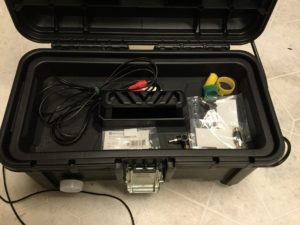
Some sort of housing for the driver, switch and optional dimmer. I used a toolbox so I could store my RCA cables and accessories in it but you can use any type of project housing or even a speaker (details on that further down).
Item 1: The Sticks
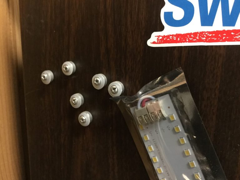
The panels will arrive with little magnets fastened through them with phillips screws. Unless you’re planning on using a steel surface to mount the sticks, remove these magnets and stick them to your fridge for another project.
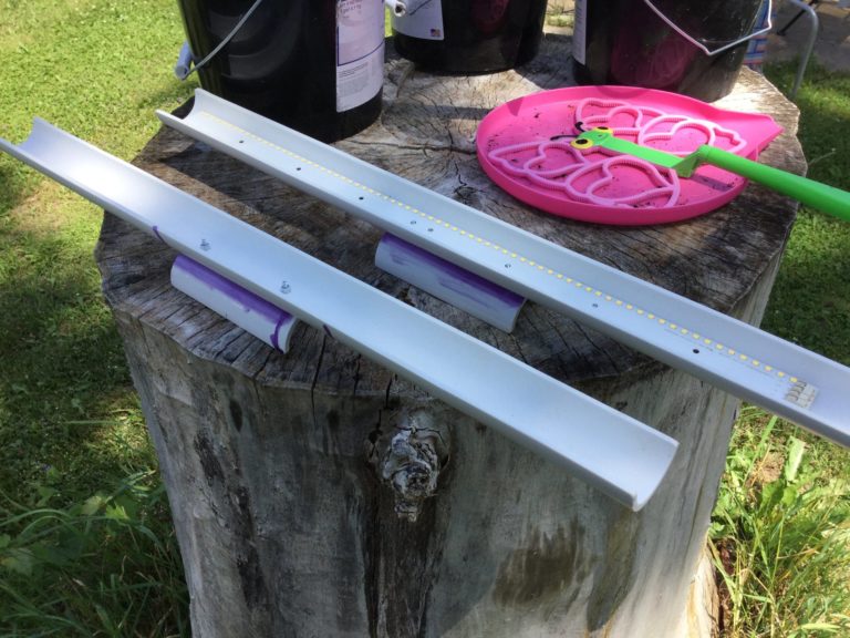
The next step will be to cut the 2-foot length of 1 1/2″ PVC pipe directly in half down the center. The method I used for this involved a table saw and two small bar clamps and I do not recommend it. Consider a bandsaw or a red-hot wire instead. PVC pipe can shatter explosively if it binds with a rotating object.
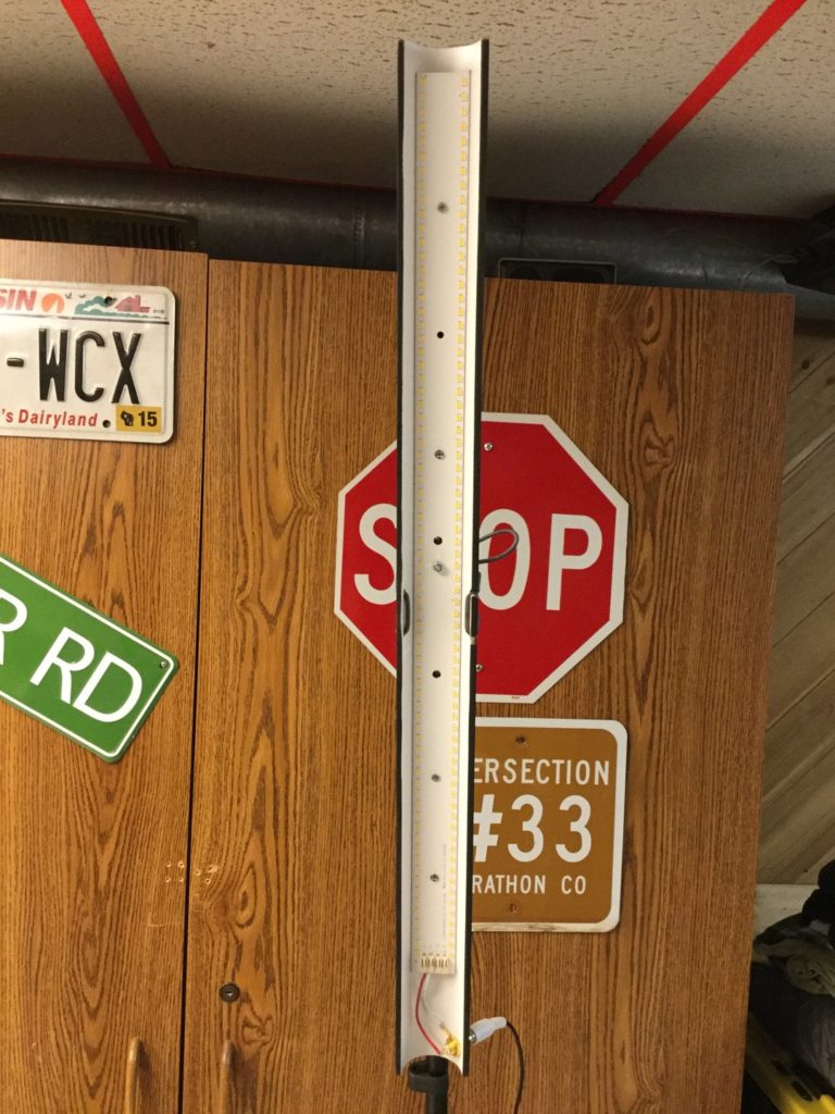
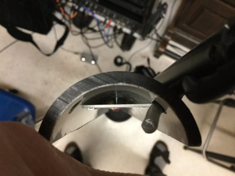
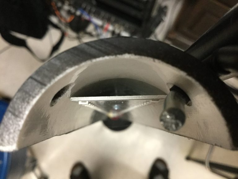
Anyway, after you’ve got the pipe cut into two nice troughs, lay a light panel into each one, determine where it should rest in the trough and use a drill bit through the holes to mark your locations for the panel retaining bolts. The panels have seven holes in them but you don’t need seven bolts. Four is more than enough.
Note that the lighting panel should not be centered in the length of the trough. Decide how you’ll want to mount the light sticks and determine your panel’s spacing from there.
In these two pictures you can see that the panel is spaced about 1/2″ down from the top of the trough on the rear-mounted stick, but closer to 1″ down on the hanging stick to allow room for the hanging holes at the top.
In both cases, the panel is spaced well above the bottom of the trough to allow generous space for the RCA power input.
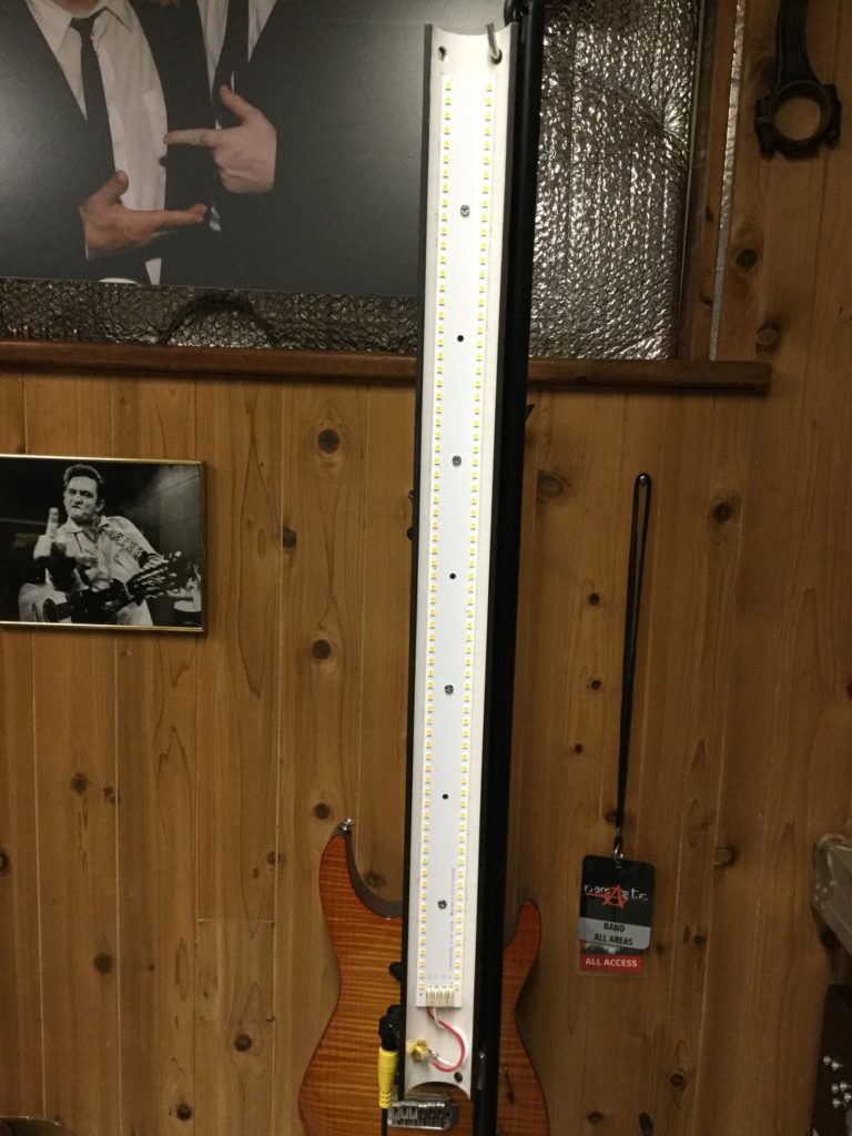
Below are a couple photos showing how the panel lays in the trough. The edges rest against the PVC and the bolts run down the center, so be careful not to over-tighten the bolts when you get to the installation phase or you could easily bend the aluminum panel. The nylock nuts will allow a snug fit without rattling loose over time.
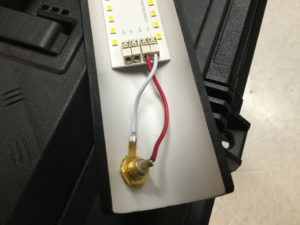
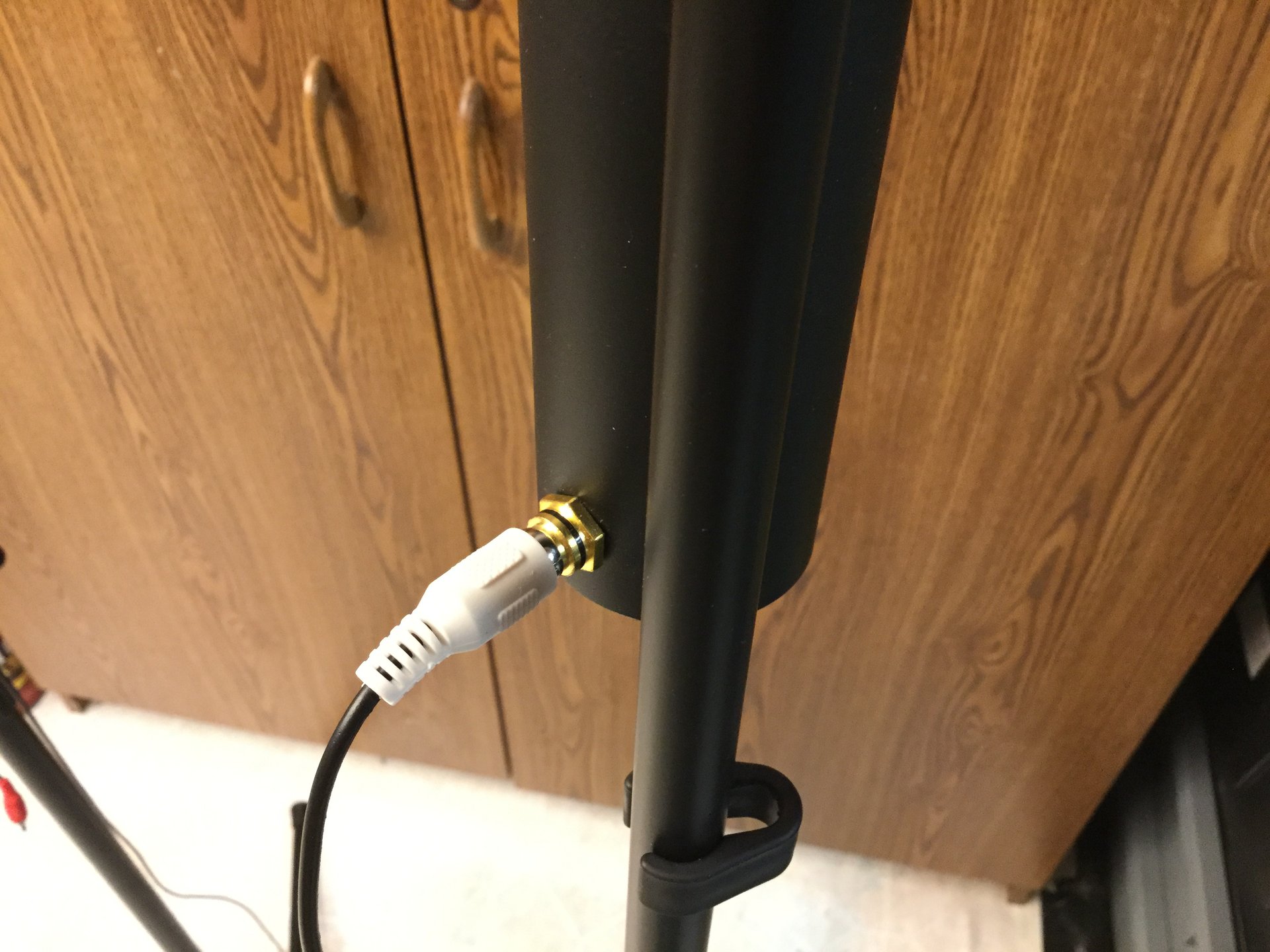
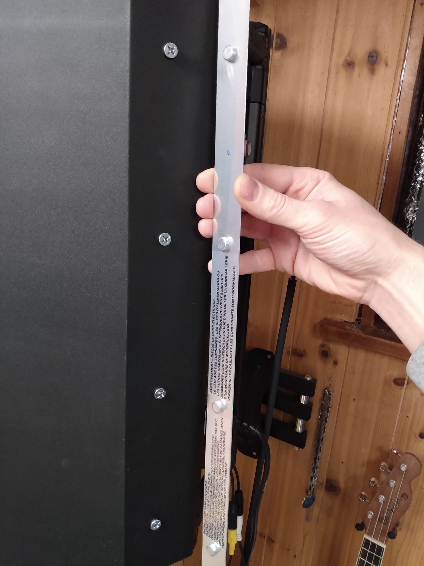
Before you get to the finishing stage, you’ll need to drill a hole for the RCA jack which will provide power. I recommend off-setting this hole from the centerline of the trough in order to avoid the possibility of your power cord hitting whatever you have the light stick mounted to. If you’re building two light sticks, you might consider offsetting each one in the opposite direction to make mirror options for right and left.
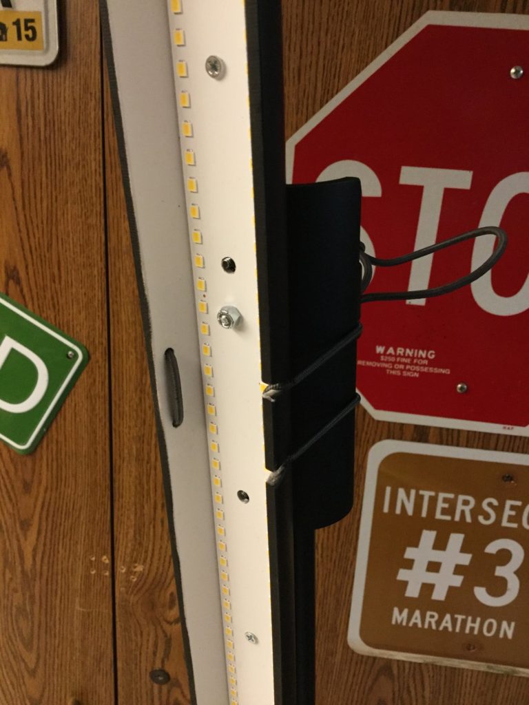
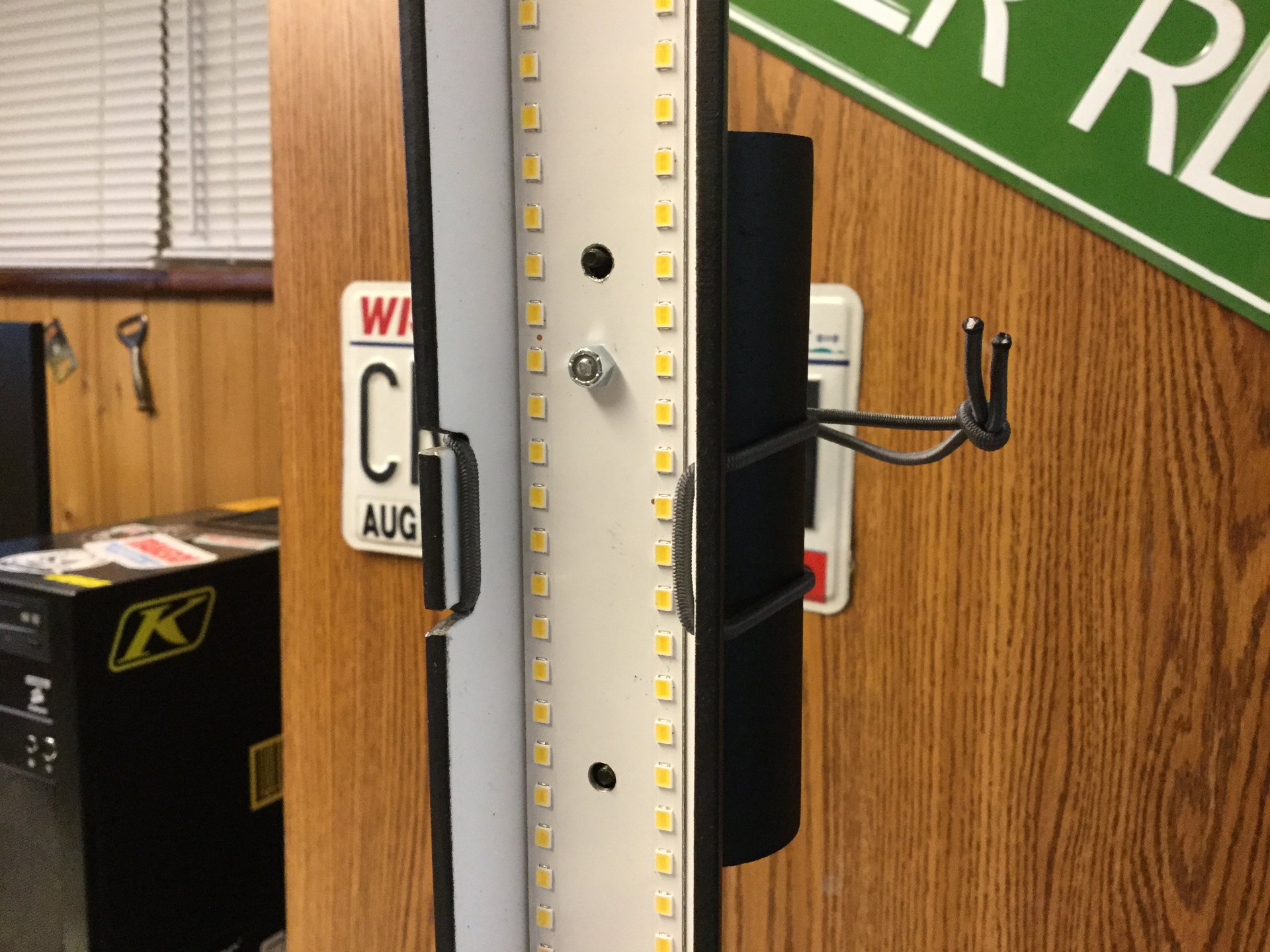
This power input is offset to avoid conflicts with the supporting spar.
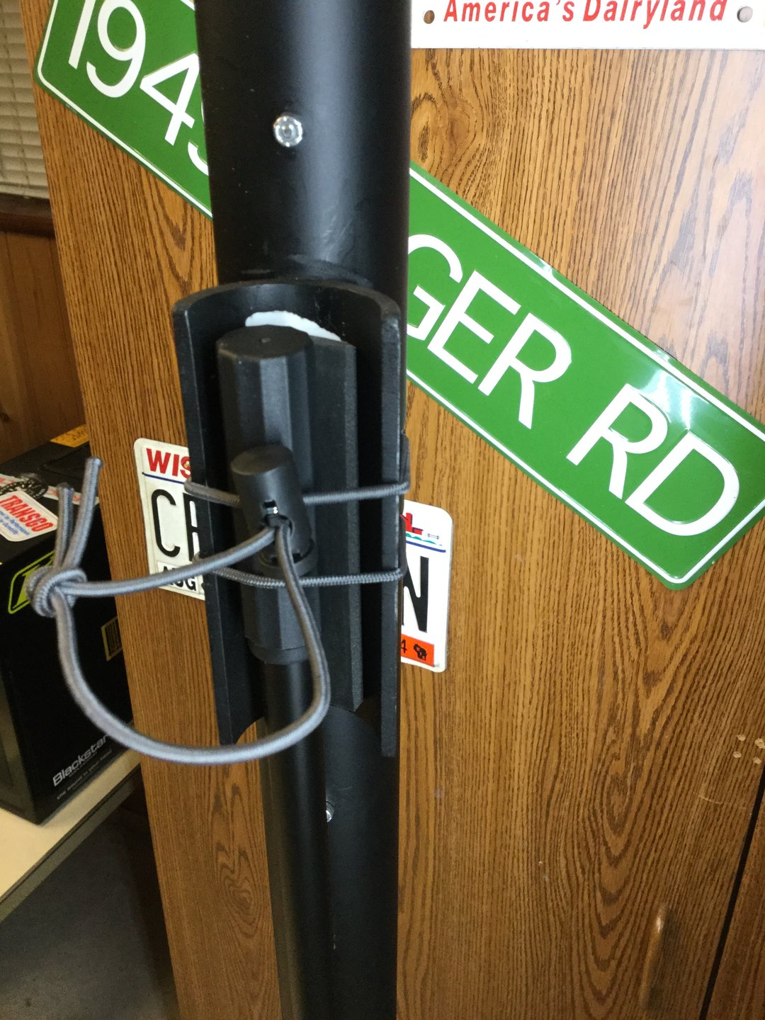
Here is a pair of light sticks, note how the RCA power inputs are mirrored as well as the notches for the retaining shock cord.
Mounting the Sticks
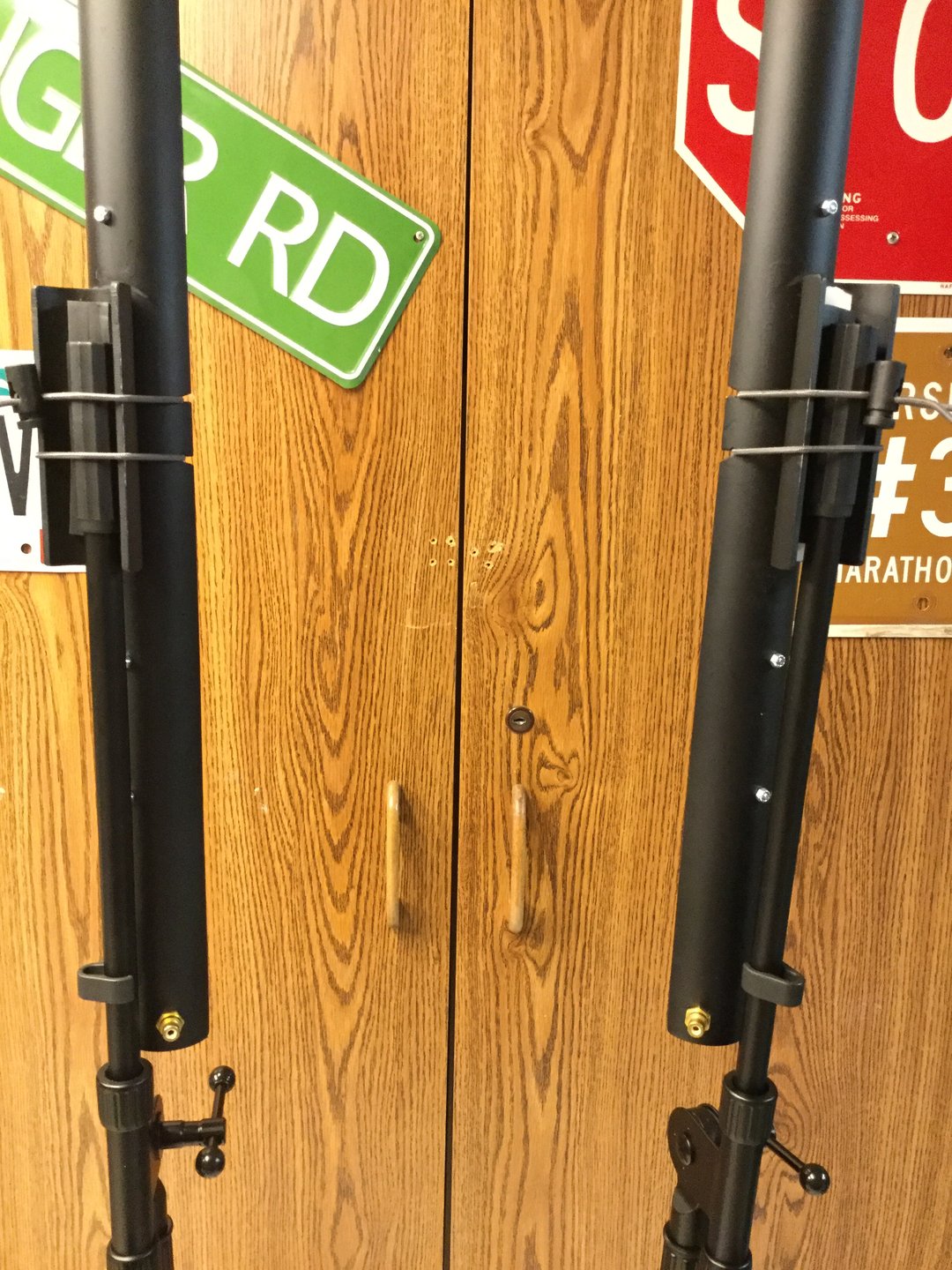
Mounting solutions will vary depending on your application. My original set used s-hooks to hang the sticks, and my second set was designed to strap onto speaker poles or microphone stands. I think the second solution was more versatile and overall more useful so I’ll concentrate on the details of that one.
The photos above show the simple arrangement for securing the sticks to a pole or mic stand. Note how the shock cord passes through two holes in one side of the trough but passes through two notches on the other side. This is to allow the sticks to be quickly attached and detached without having to adjust the tension of the shock cord. So once the tension is adjusted for a particular size of pole, it’s simply a matter of holding the light stick against your mounting point and hooking the shock cord into it’s notches.
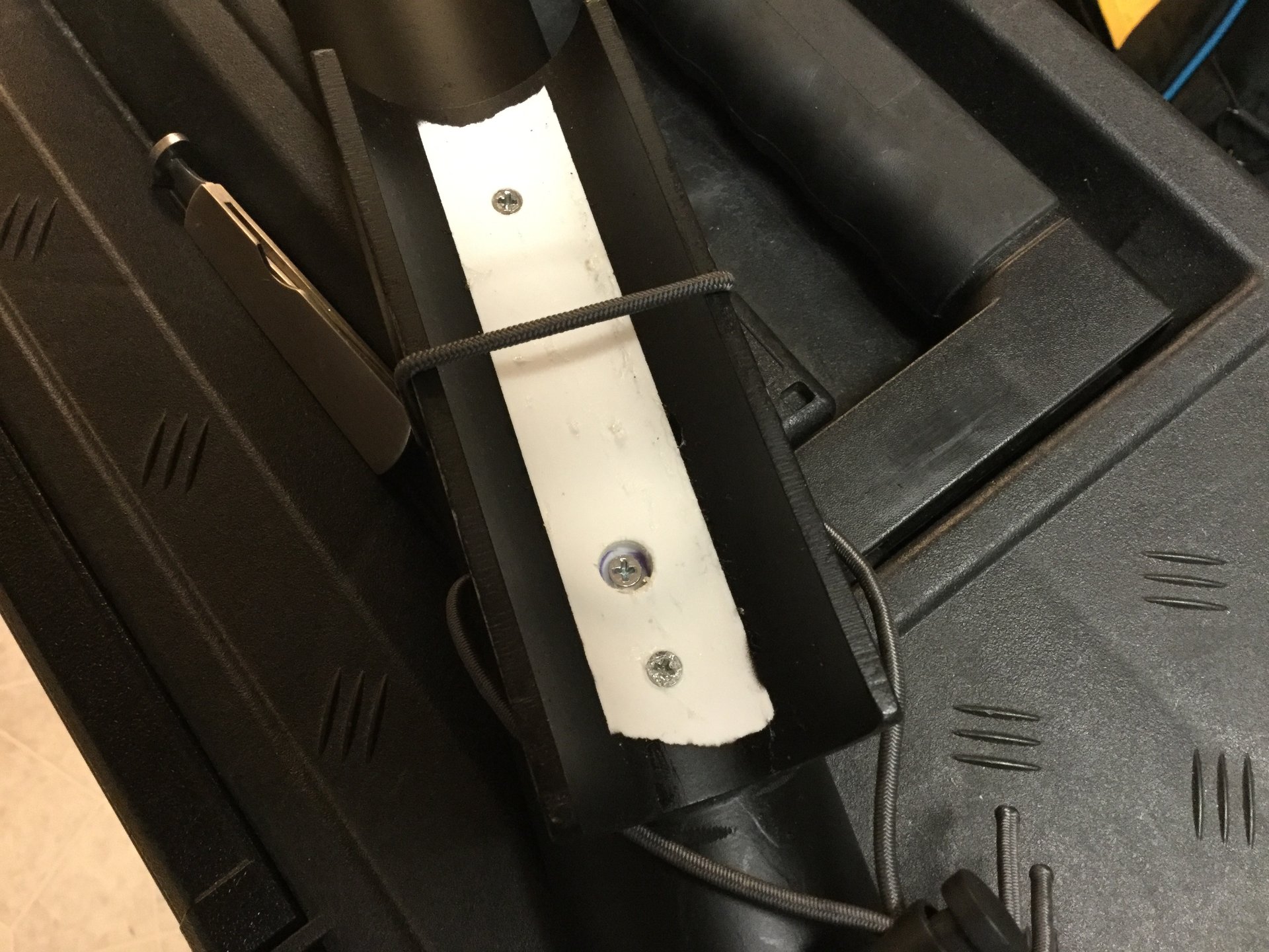
To make the mounting channel, take a section of 1 1/2″ PVC pipe and slice it longitudinally like you did for the lighting troughs. I used two 4-40 machine screws with locknuts as well as PVC cement to secure the mounting channels to the back of the troughs:
Then I drilled and milled the holes and notches for the retaining cord as described above.
After all that is done and the holes for the panel screws and RCA power jack have all been drilled, it’s time to finish off all the sharp corners with sandpaper, prep mask and paint. Mask off the inside of the troughs to maintain maximum reflectivity and at least partially mask off the inside of the channels so you have a clean surface to stick your liner/backing pad onto later.
In these two photos you can see the two countersunk retaining screws for the mounting channel, as well as a third deeply-sunk screw which is one of the light-panel screws. This third screw is probably unnecessary and results in an incongruous exposed nut on the light panel since it must be installed in the reverse direction from the other light-panel screws.
In the second photo you can see the two tips of the channel retaining screws protruding through the lighting panel. Why I chose to drill holes in the panel instead of simply cut down the screws is beyond me.
Note the exposed white section of pipe inside the mounting channel. This was masked off during painting to offer a clean surface for the channel’s grippy backing pad to stick to.
DON'T DO THIS
I used bits of foam rubber weather stripping as a backing pad for the mounting channels and it fails.
The weather stripping is designed to seal, not grip, and it’s soft gummy backing adhesive shears incredibly easily. Here you can see that the strip has already shifted sideways after minor handling.
I recommend cementing a piece of rubber inner tube to the inside of the mounting channel instead of the weather stripping.
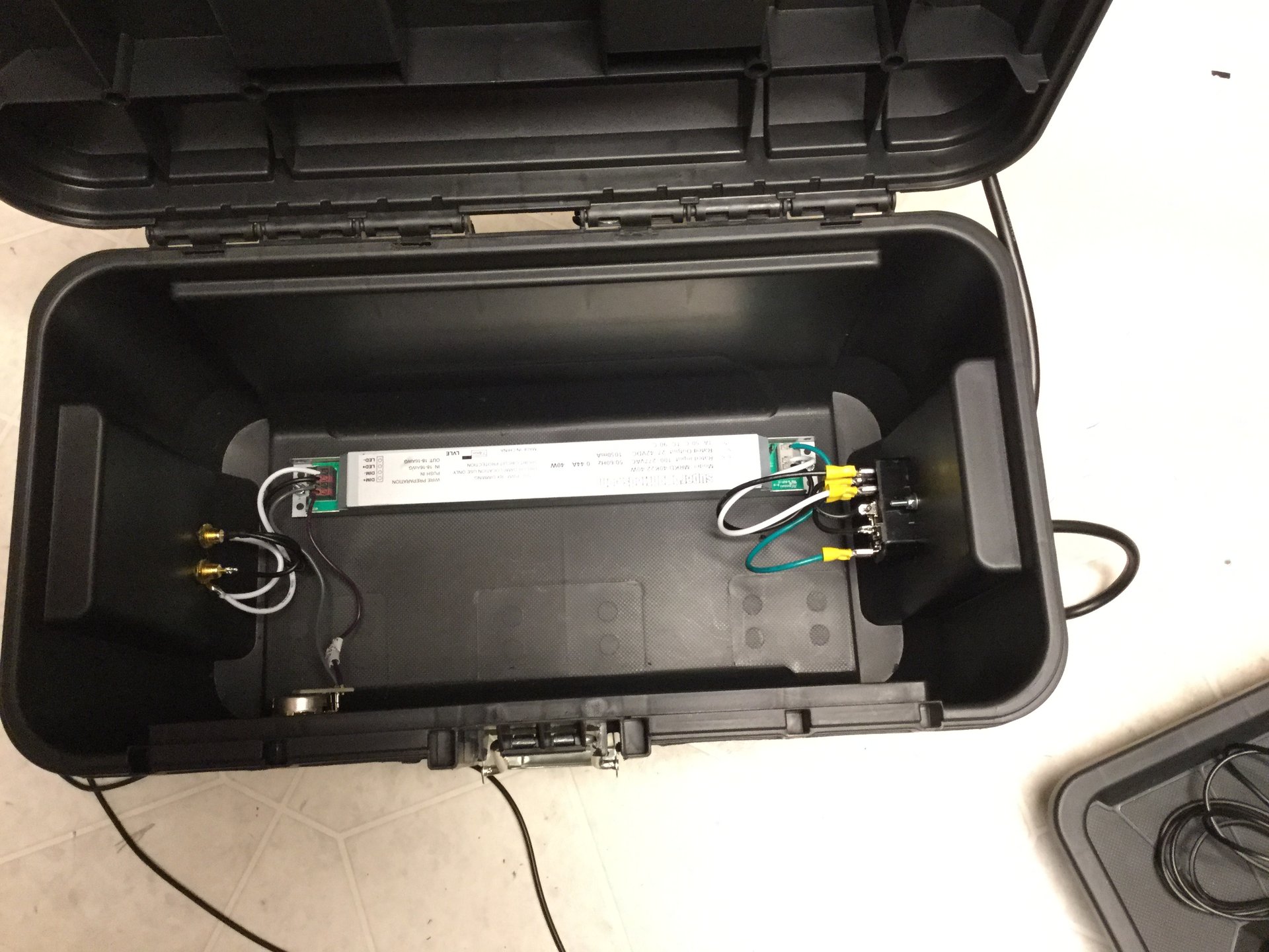
Item 2: The Driver/Switch Box
The driver, power switch and optional dimmer are all housed in a small enclosure of some type. For maximum versatility you can use a small toolbox, which doubles as a space to store your RCA power cables, connectors and IEC power cable. This is how one of my light stick rigs is set up.
For the other I chose to incorporate the power apparatus into a PA speaker since it’s intended to be lighting for live performance.
Both methods are basically similar and quite simple. Click on any of the pictures below for a full-size version.
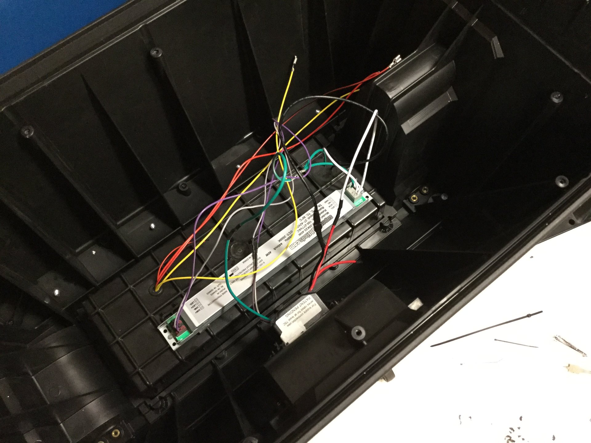
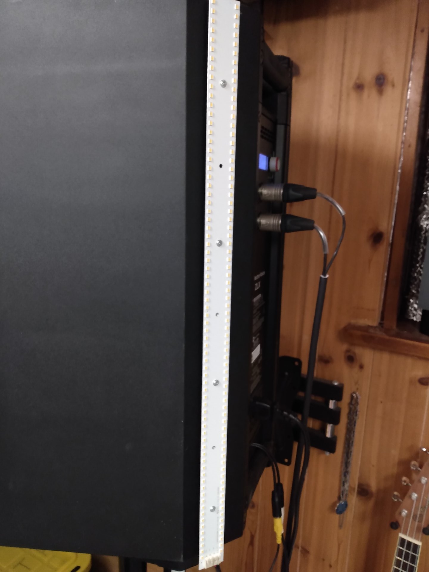
Power input is on the right, output is on the left. The thing on the front of the box toward the bottom of the pic is the dimmer.
The upper tray of the toolbox is where I store my power cords, RCA butt connectors and spare fuses.
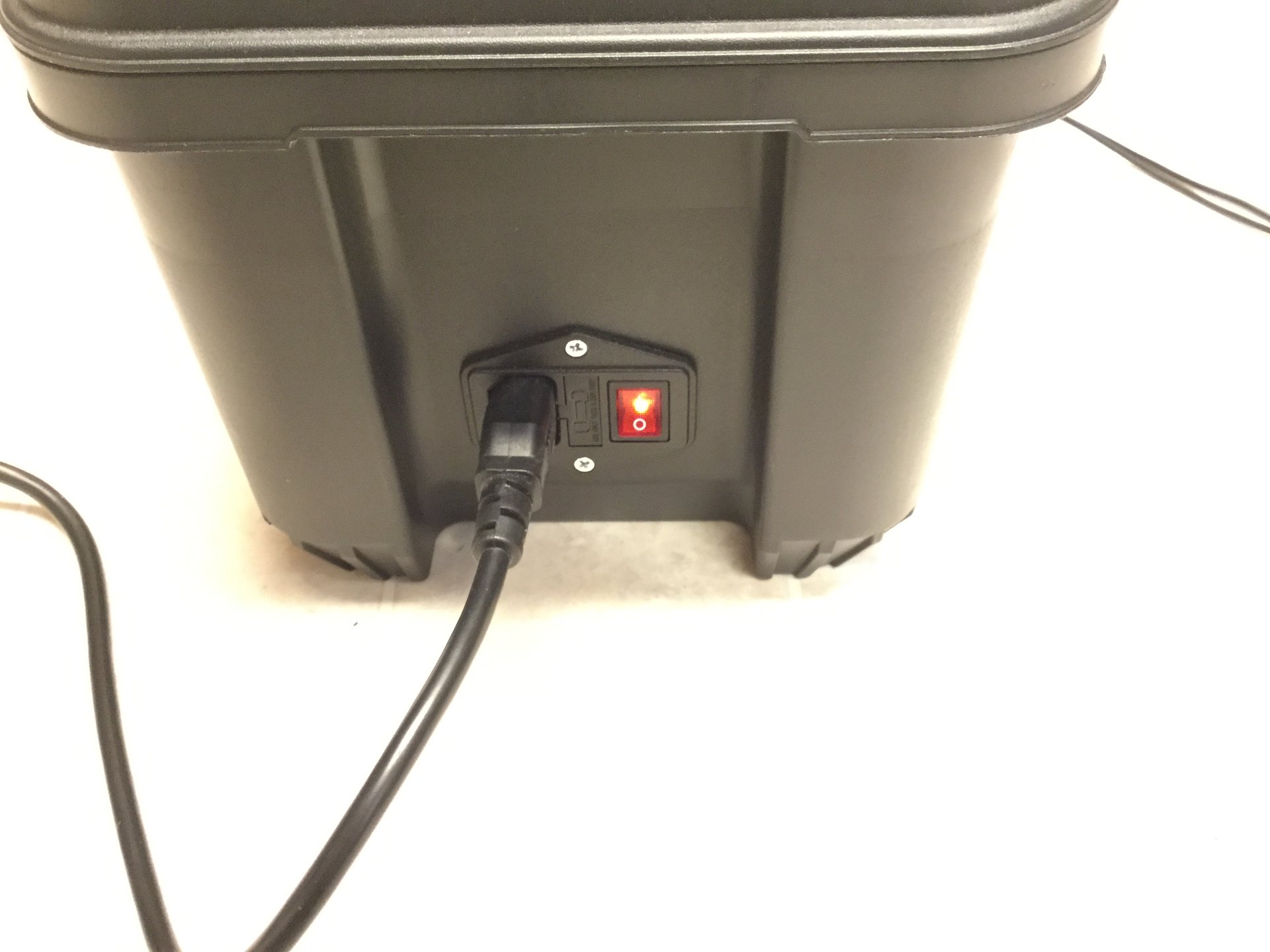
Input end.
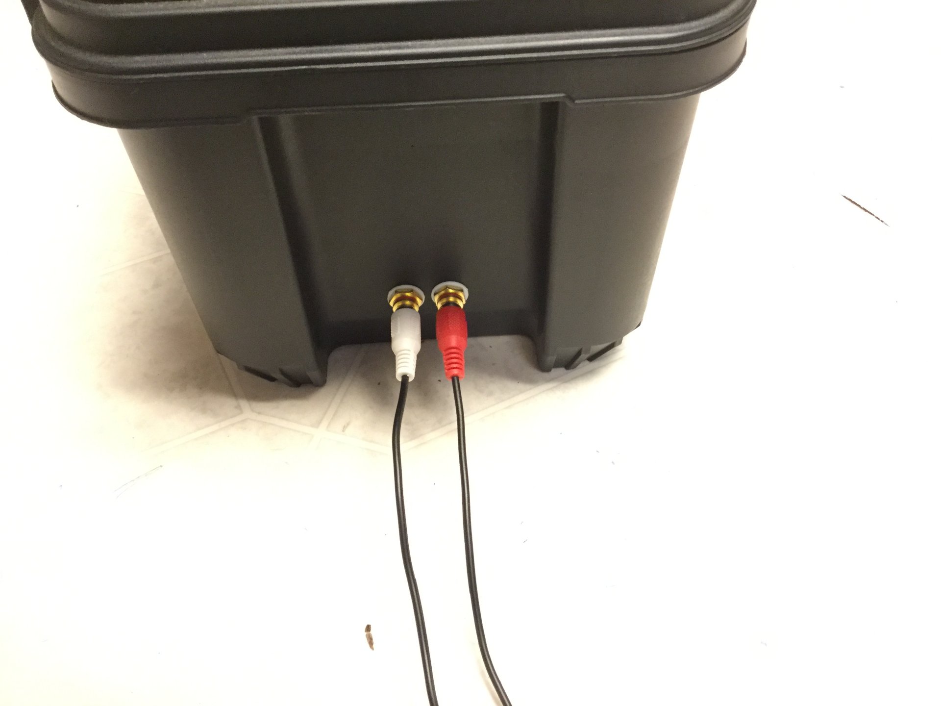
Output end.
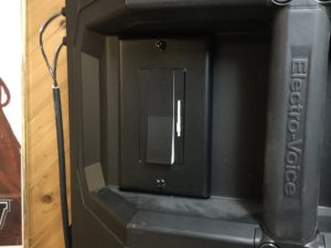
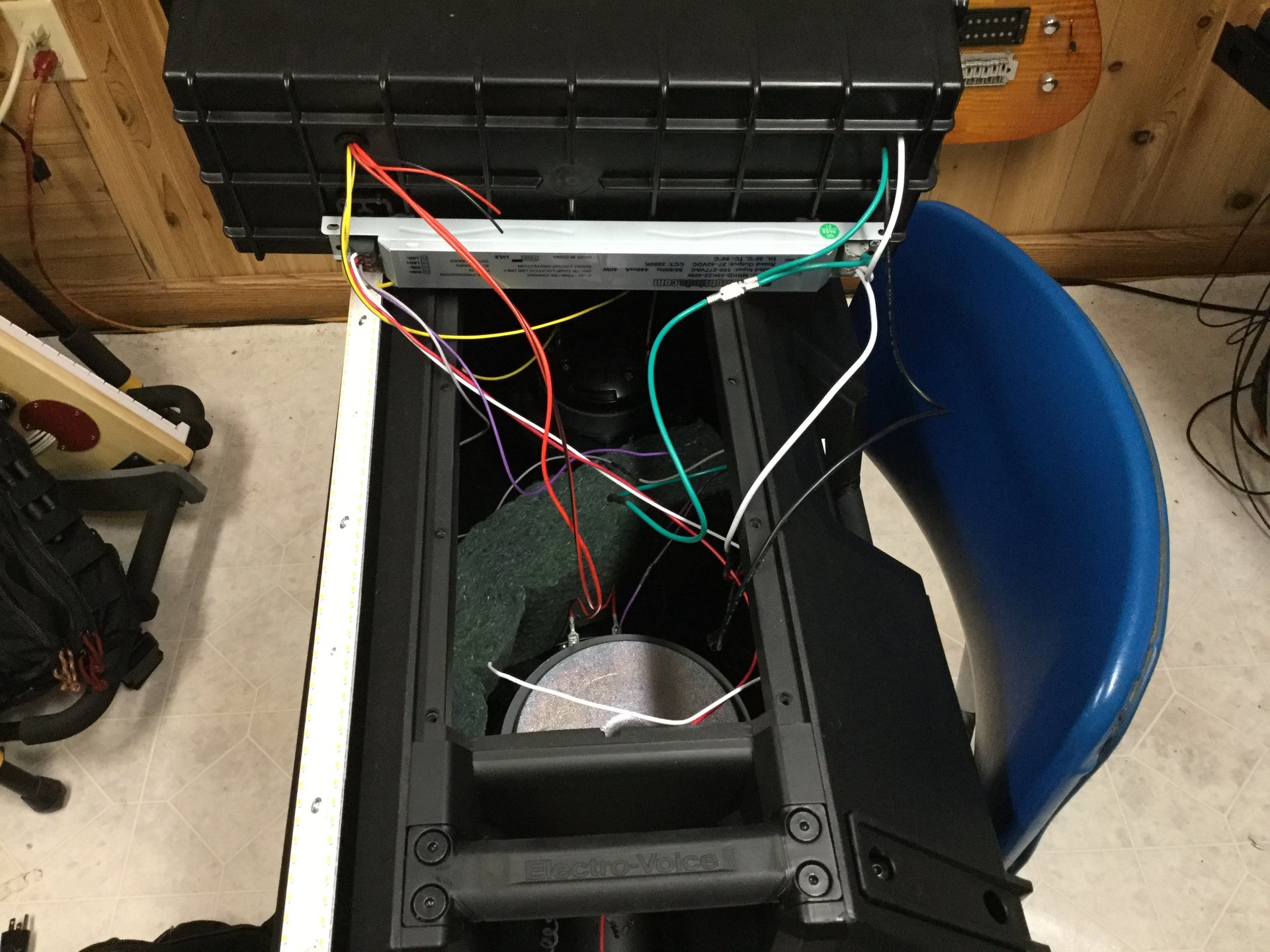
For mounting inside my speaker, I fastened the driver to the back of the amplifier enclosure. The dimmer/switch combo fits neatly behind the side handle of the speaker (EV ZLX-12)
View of the speaker mount from the front with the grille and speakers removed.
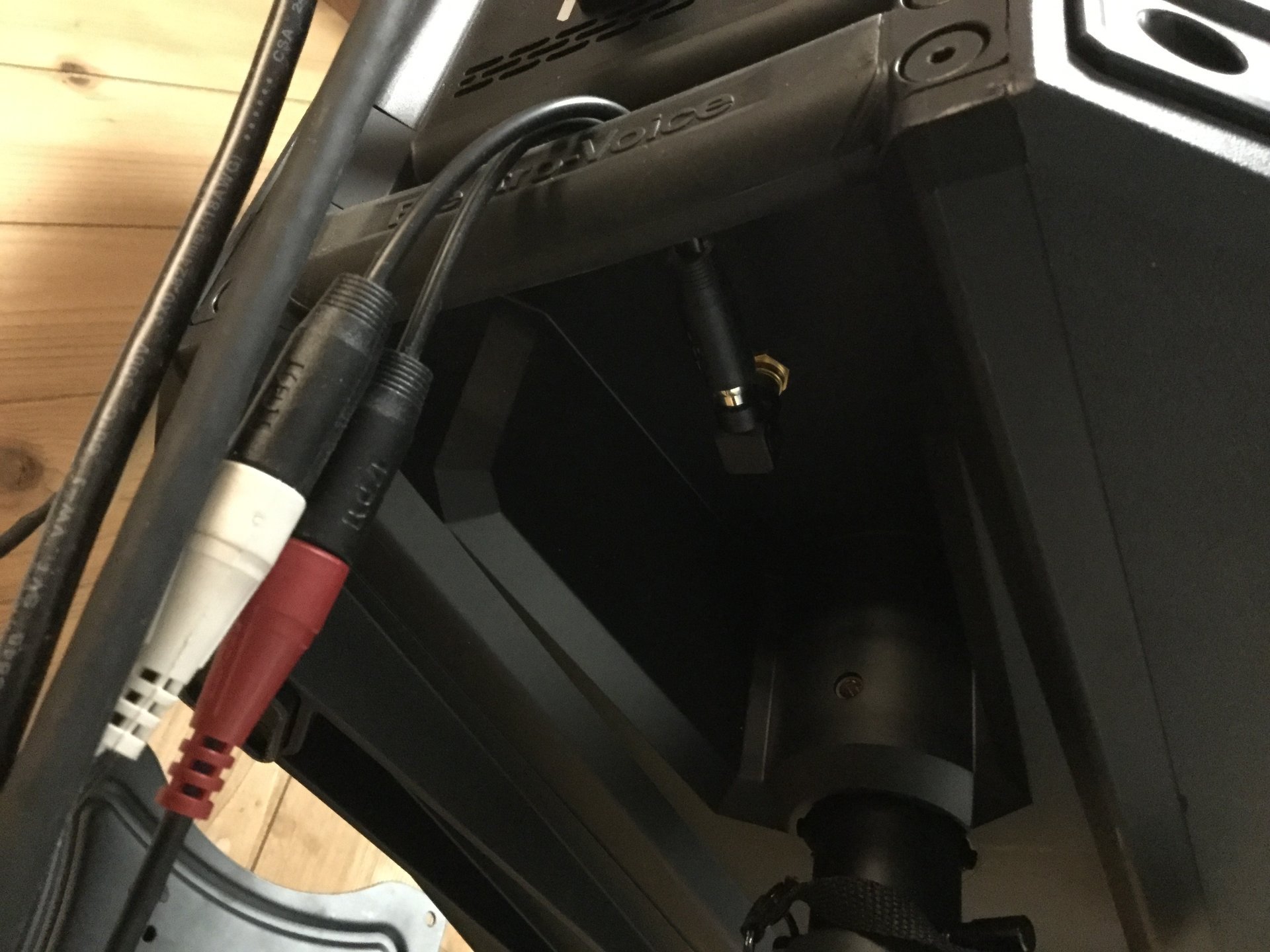
The output from the speaker is on the bottom, just aft of the pole mount. It’s a single RCA jack that can be y-ed off into multiple lights.
The switch/dimmer combo lives on the right side of the speaker, inside the handle well.
This bare panel has the magnets intact and is mounted to the conveniently-angled rear quarter of the speaker in order to illuminate the performer behind and to the side of it.
The magnets on the panel cling nicely to four large flat-head screws fastened into the speaker housing.
I think that about wraps it up for the light-stick project. As always, if you require clarification or have ideas for improvements, don’t hesitate to contact me.