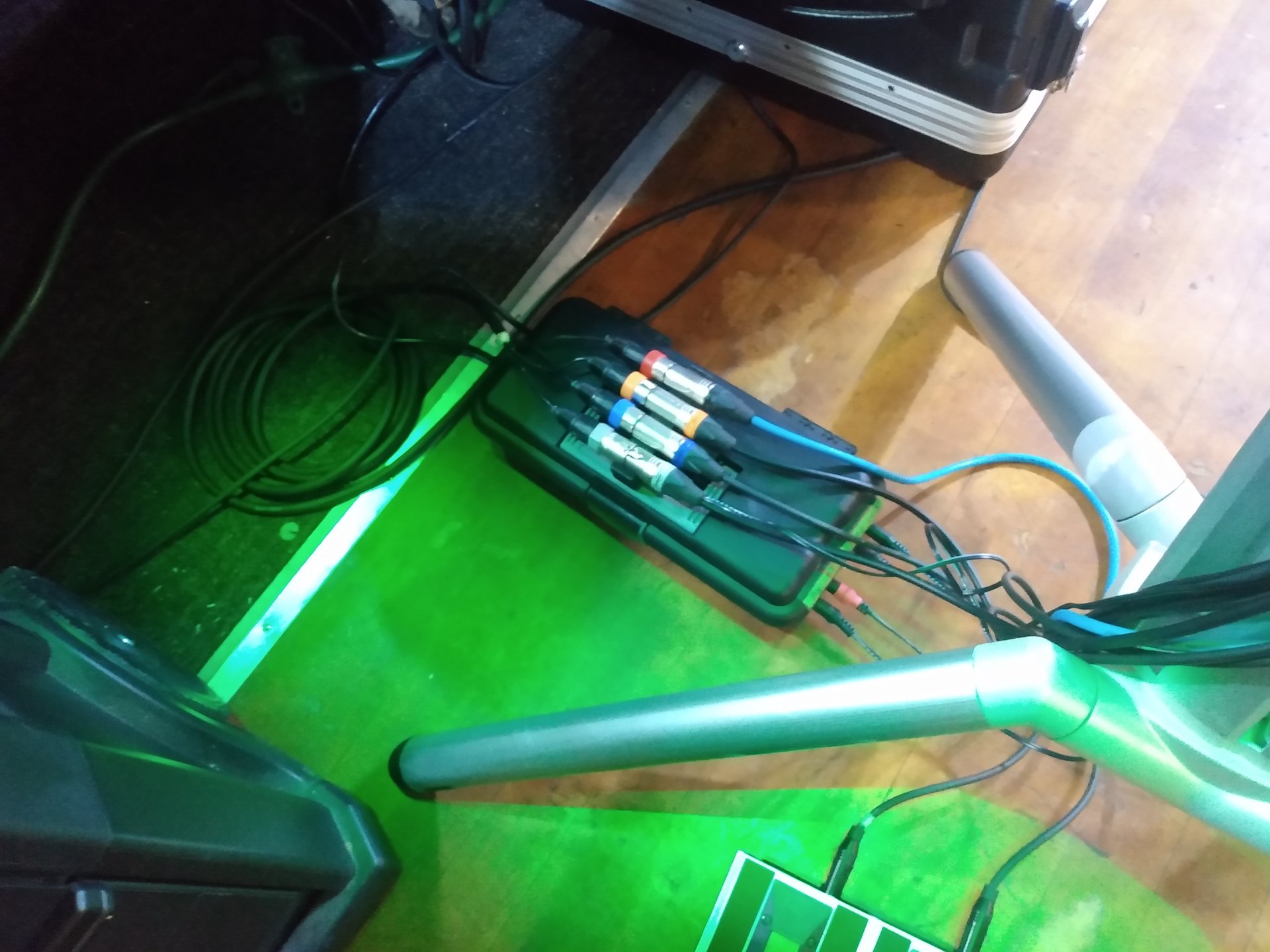
The Power Box is a simple concept to consolidate the multiple DC adapters required for my keyboard rig into a streamlined container, to boost setup and teardown speed and also to clean up the stage a little.
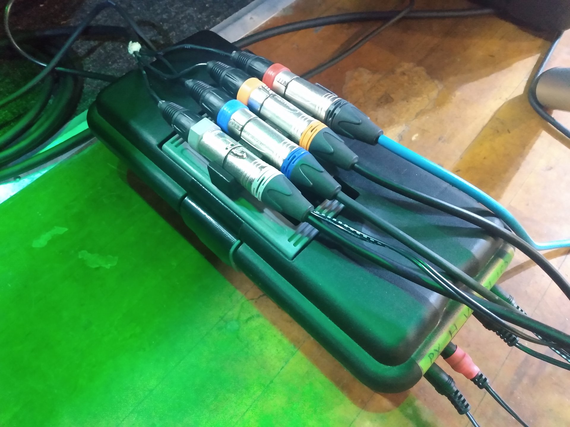
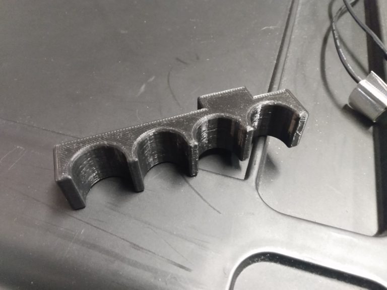
I also 3D-printed a small loom to organize my 4-channel snake leads on top of the box.
If I missed anything or you have any questions, feel free to get a hold of me and I’ll do my best to fill you in.
IMPORTANT: This is a general overview and concept of the project, with basic tips on construction. This is not a step-by-step guide. Do not attempt if you have low intelligence or lack a basic knowledge of how AC and DC power work.
Rudimentary soldering skills and basic power tools are also required.
WHAT YOU’LL NEED:
Enclosure (I used a small plastic tool box),
Panel-mount barrel jacks (This is what I used but there are other variations on the site),
Extension leads (This will vary with your device, 2.1mm x 5.5mm barrel connectors seem to be most popular at least in the United States. Here‘s the one I used most.)
Double-sided mounting tape, hot glue or other means of securing everything from rattling,
4-40 flat head machine screws with nuts to mount the IEC jack (qty 2),
A power strip that fits into the enclosure,
And I recommend some type of master switch to shut off the main power. I used a basic SPST toggle switch that I found laying around, just make sure it’s rated for AC voltage and a few amps of current.
The construction is mostly self-explanatory from the pictures, but there are a few things to be aware of before you begin.
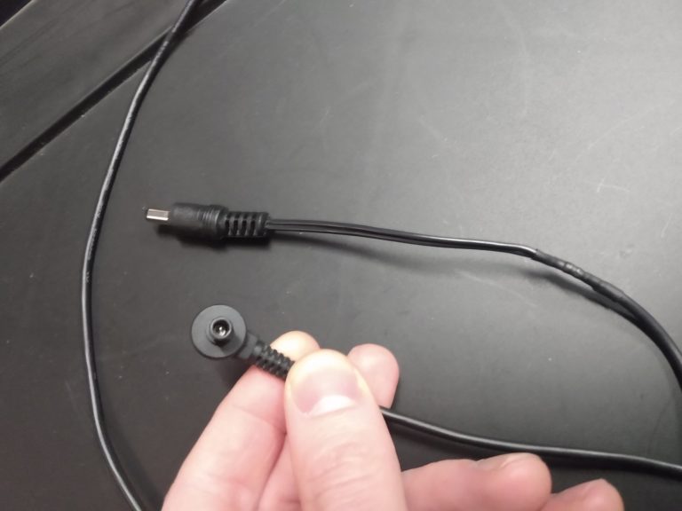
Firstly, note that you’ll be cutting the ends off of your device’s power supplies in order to solder them onto the panel-mount jacks inside the enclosure. This is, obviously, a permanent modification and will probably void your device’s warranty.
Before mounting up the power strip inside the enclosure, you’ll want to disassemble the power strip and completely remove it’s cord. The cords on these are usually ponderous and stiff and space is at a premium inside the enclosure. Strip it apart and use short sections of the conductors to jump from the IEC jack and switch to the power strip.
Pay attention to the size of the jacks and cords that you’re ordering. While the outside diameter of most barrel connectors are similar, the inside pin has two standard diameters: 2.1mm and 2.3mm. They are not interchangeable. I went with 2.1mm as it seems to be more popular where I live.
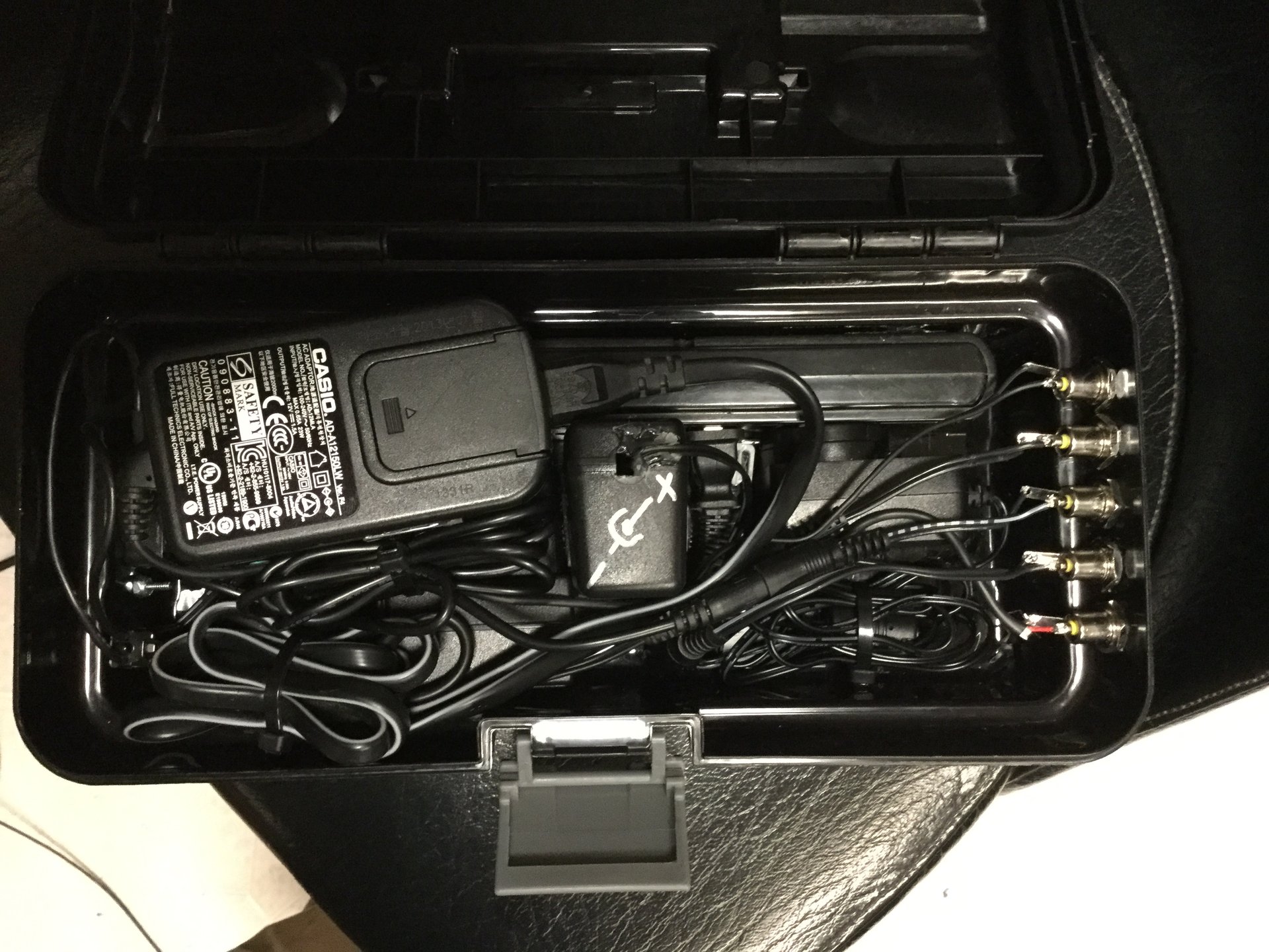
Everything is secured with 3M mounting tape and zip ties to prevent any movement inside the box. IEC input and switch are at the left, partially obscured by the Casio adapter. Outputs are at the right. The power strip is partially visible at the top.
If your device has a non-standard plug, you’ll need to use the cord that you cut off of it’s adapter and splice a barrel connector to the cut end in order to connect to the power box’s output. This is also an opportunity to precisely adjust the cable’s length for your application.
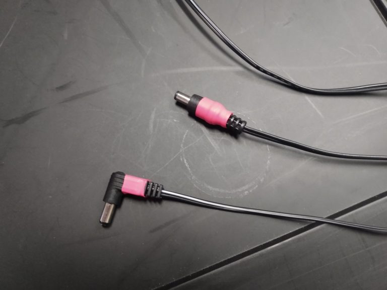
It’s a good idea to color-code both ends of your output cables so you can tell at a glance which cable is plugged in to which output on the box. I used short cuttings of colored heat-shrink tubing here.
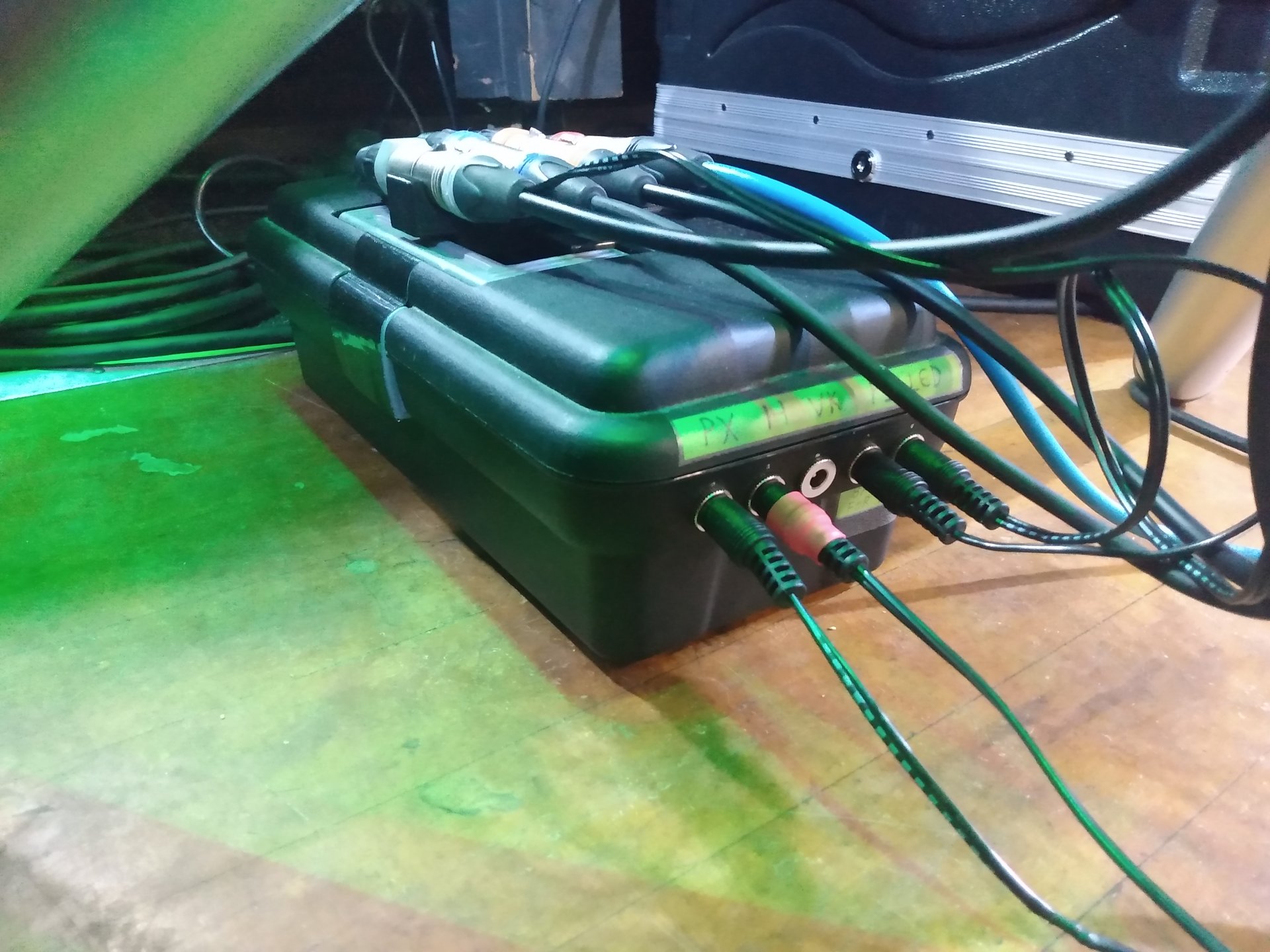
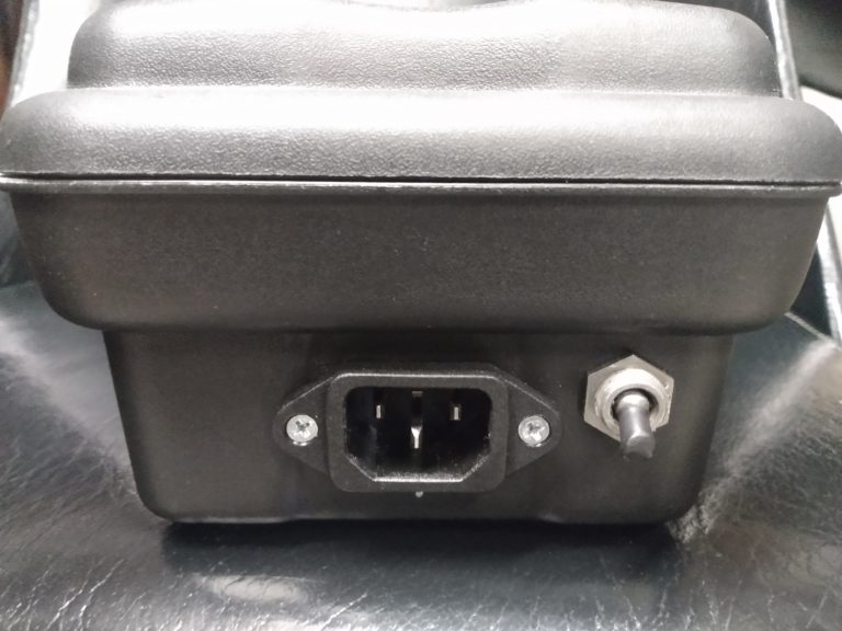
Here’s the input end of the box with it’s IEC jack and master power switch.
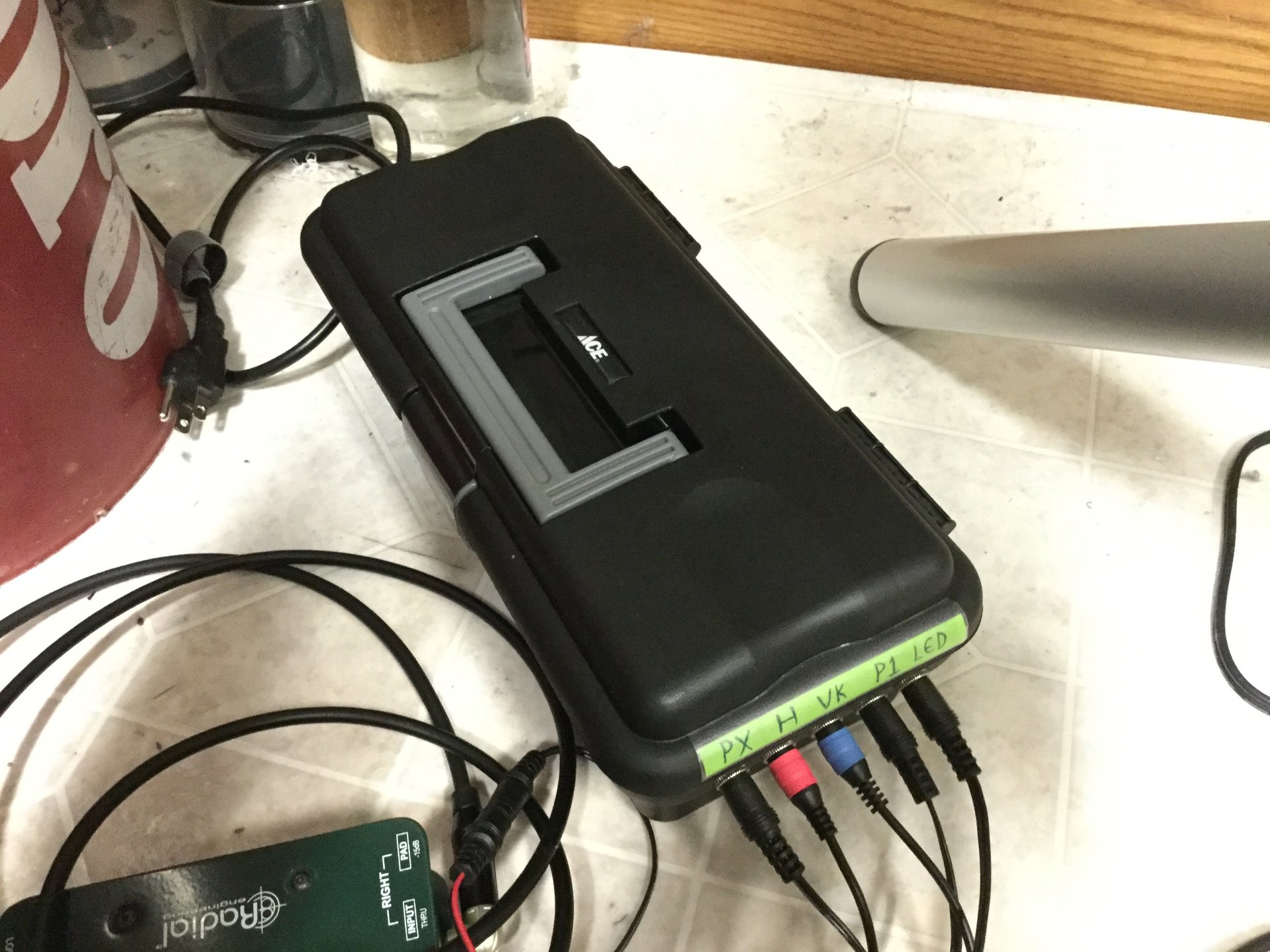
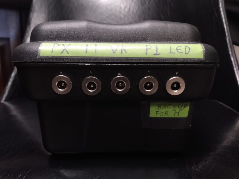
Here’s the output end. It’s important that the outputs be labeled since each output carries the specific voltage and polarity required by it’s device.
I printed a simple loom to clean up my audio snake as well, it sits on top of the box. If you want the gcode for this, drop me a line and I can send it to you.